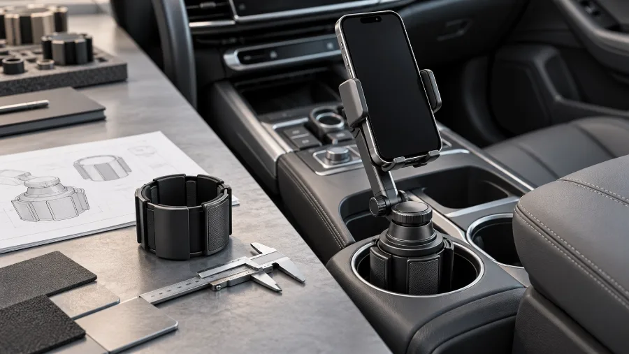
The short answer: approve a cup holder phone mount base only after checking the target vehicle's cup-holder diameter, depth, taper, liner, position and nearby controls with the complete holder, phone and case installed. An expanding base can avoid the windshield and air vent, but it is not automatically universal. Stability depends on the actual cup-holder geometry, expansion mechanism, arm leverage and repeatable installation.
This guide is for importers, distributors, private-label brands and sourcing teams comparing cup-holder-mounted phone solutions for OEM or ODM programs. It focuses on the base-to-vehicle interface and the production controls needed to keep the approved fit consistent.
Treat the product as one system: cup-holder base, expansion parts, arm, joints, holder head, phone, case, cable and vehicle console. A pass result from one combination should not be transferred to another without checking the changed parts.
Quick decision guide
Consider an expanding cup-holder base when the target cup slots provide a defined contact area and the base can lock without bottoming out, deforming the liner or relying on extreme tightening. The installed arm should remain clear of controls and should not turn normal phone use into excessive leverage on the console.
Choose a different vehicle interface when the cup holder is unusually shallow, strongly tapered, removable, obstructed by a lid, positioned beside critical controls or required for drinks. A vent, dashboard, windshield or screen-mounted base may be more suitable than forcing a cup-holder claim.
Why cup-holder mounts need a dedicated compatibility review
A cup holder is not defined by one diameter. It may have a wider opening, narrower lower section, flexible fingers, a removable insert, an angled wall or a non-circular shape. Two cup holders with similar openings can support the same base very differently.
Location matters as much as geometry. Some cup holders sit low, under an armrest, behind a selector or beside a console switch. The base may expand securely yet still create poor viewing, difficult reach or interference with normal vehicle use.
1. Build a vehicle cup-holder matrix
List the vehicle brand, model, model year, market version and exact cup-holder position. Photograph the cup holder from above and from the side, including the surrounding console, armrest, selector, brake controls, lids and storage areas.
Measure the opening, lower diameter, usable depth, taper and any change in shape. Record whether the cup holder is round, oval or segmented, and whether flexible tabs or a removable liner affect the contact area. State where every measurement was taken.
Mark unknown dimensions as open items. A vehicle name, cup-holder photo or nominal diameter alone is not enough to approve fit. Use representative fixtures or physical vehicles for the final sample decision whenever possible.
2. Verify the expansion mechanism
Identify how the base expands: moving segments, wedges, a screw-driven sleeve or another mechanism. Check the starting diameter, useful expansion range and the position of each contact pad in the target cup holder. Supplier terminology should be supported by a drawing or sample.
Confirm that the mechanism locks within its intended working range. A base that reaches the cup-holder wall only at the end of its travel may have little adjustment margin. A base that expands too early may not enter the cup holder deeply enough.
Observe whether tightening lifts, tilts or rotates the base. The installed centerline and contact pattern should remain controlled. If a knob or screw provides adjustment, evaluate access, turning clearance and how the user recognizes the locked condition.
3. Check contact pressure and surface protection
Inspect every expanding segment, edge and pad. Contact materials should stay in position during tightening, use and removal. Look for sharp molding edges, exposed fasteners, concentrated pressure points and hard surfaces that can polish, cut or deform the cup-holder liner.
Test repeated installation and removal, then inspect both the base and vehicle fixture. Define acceptable marks, pad movement and liner deformation before approval. Do not use a general no-damage statement without a named fixture and test method.
4. Test rotation, lift and lateral movement
A cup-holder mount sees more than downward load. Phone insertion, removal, screen tapping and arm adjustment can apply twisting, sideways and upward forces. Observe the base while performing the intended user actions, not only while the phone sits still.
Record whether the base rotates in the cup holder, climbs upward, rocks on the rim or loosens after repeated use. Separate movement at the vehicle interface from movement in the arm, joints and holder head so corrective action targets the correct component.
5. Evaluate arm length and complete load
Test the base with the approved arm, joints, connector, holder head, phone or defined test load and case. An empty base can appear stable while the complete assembly rotates or sags because the phone sits higher and farther from the cup holder.
Longer or telescopic arms improve reach but increase leverage. Test the shortest, typical and maximum approved positions in portrait and landscape orientation when both are claimed. Record angle drift and base movement separately.
Confirm that the arm does not need extreme joint tightening to compensate for an unstable base. A strong holder head or stiff ball joint cannot correct poor engagement at the cup-holder interface.
6. Check console and control clearance
Install the complete product and operate nearby selectors, parking-brake controls, start buttons, storage lids, armrests and the second cup holder where applicable. Check seat movement and passenger access if the mount extends into shared space.
Evaluate the viewing position without blocking essential vehicle functions. A high arm may improve visibility but create interference; a low arm may preserve controls but make the phone difficult to see or reach. Approve the position as part of the configuration.
Decide whether losing one cup holder is acceptable for the target customer and sales channel. If the design includes a tray or preserves secondary storage, test that feature with the mount installed rather than relying on packaging claims.
7. Confirm phone, case and holder-head fit
Define phone width, thickness, weight, button position, camera area and case type. Screen size alone does not define the phone's external dimensions. Include the thickest and heaviest agreed configurations in sample approval.
Validate magnetic, clamp, gravity or automatic holder heads with the selected base. One-handed phone insertion or removal may apply torque to the arm and cup-holder interface, so user operation must be part of the complete-system test.
8. Include cable, charging and cleaning conditions
For wired or charging versions, map the cable route to the vehicle power source. The cable should not pull the mount, cross a selector, become trapped by a lid or interfere with normal console use. Confirm the included cable and connector orientation.
Cup holders may collect dust, liquid or debris. Define cleaning and installation instructions appropriate to the product materials. If the base blocks access to the cup-holder bottom, consider how users remove and reinstall it without damaging pads or losing the approved setting.
Charging performance, thermal behavior and electrical compliance are separate from base stability. Request evidence only for the exact charging module, cable and market configuration included in the project.
9. Make installation repeatable
Define the insertion depth, tightening sequence, locked-state cue and removal method. Different users should be able to reach the same stable condition without hidden tools or excessive force. Record the number of steps and likely installation errors during sample trials.
Instructions should show compatible cup-holder examples, unsuitable shapes, correct pad contact, arm positioning and warnings against overtightening. Do not rely on a universal label when fit depends on measurable geometry.
Package the correct base, arm, connector, holder head, pads, tools and instructions for the approved configuration. Similar-looking bases with different expansion parts or arm lengths need controlled model identification.
10. Define durability and production controls
Write the test setup, sample quantity, conditions, duration and pass criteria before mass production. The plan may include repeated installation, tightening cycles, phone operation, adjustment cycles, representative vibration, static holding observation and post-test inspection. This guide does not prescribe unsupported universal numbers.
Mark the approved sample and define critical characteristics: expansion range, contact geometry, pad location, screw or wedge travel, arm length, joint interface, fastener engagement and cosmetic limits. Decide which items require measurement, functional checks or visual inspection.
Control changes to plastic, metal parts, pads, springs, screws, lubricant, mold, supplier and assembly method. A small change can alter friction, expansion travel, surface pressure or long-term stability. Require revalidation when a controlled characteristic changes.
Compare common cup-holder mount configurations
A short fixed neck keeps leverage lower and can feel compact, but it may place the phone too low or too close to the console. Approve visibility and reach in the target vehicles.
A long or telescopic arm improves positioning but increases leverage and the number of joints that must remain stable. Test the complete extended configuration and control the approved arm length.
A tray-integrated or dual-use configuration can add storage value, but it changes space, load and packaging. Test the tray with the phone mount installed and include all loose parts in the packing list.
No configuration is universally best. Select the product that can document stable fit, acceptable reach, control clearance, surface protection and repeatable installation across the buyer's target vehicle matrix.
Sample approval checklist
Record the vehicle and cup-holder position; opening and lower dimensions; depth, taper and liner; expansion range and contact pattern; complete holder assembly; phone and case range; arm positions; nearby-control clearance; user-operation observations; cable route; durability setup; cosmetic result; packaging contents; open issues, owner and deadline.
Questions to include in the RFQ
The buyer should send the target vehicle matrix, cup-holder photos and dimensions, required phone and case range, preferred viewing position, holder-head type, cable or charging needs, required storage function, sales channel, packaging requirements and validation expectations.
Ask the supplier to return an interface drawing, expansion range, compatibility table, sample configuration, identified risks, test proposal, critical production controls and assumptions. Unknown fit combinations should remain open rather than being converted into a universal claim.
Common sourcing mistakes
Common mistakes include checking only the top diameter, ignoring taper and depth, approving from one vehicle, testing an empty base, using maximum tightening as the solution, overlooking selector or armrest interference, and allowing pad or expansion-part changes without revalidation.
Frequently asked question: Are cup holder phone mounts universal?
No. An adjustable diameter may cover selected cup holders, but depth, taper, liner, shape, position and surrounding controls also affect fit. Approve named vehicles or representative fixtures within a written compatibility matrix.
Frequently asked question: Is a larger expansion range always better?
No. The mechanism must operate within a controlled working range and maintain suitable contact. Maximum range does not prove stable engagement, acceptable pressure or repeatable installation in every cup holder.
Frequently asked question: Can the product keep the second cup holder usable?
It depends on cup-holder spacing, arm position, base size and phone orientation. Test the exact vehicle and complete assembly. A second cup holder that remains visible may still be difficult to use with a drink or storage tray.
Frequently asked question: What evidence should be approved before ordering?
Approve the compatibility matrix, cup-holder measurements, interface drawing, sample revision, complete assembly, installation photos or video, defined test plan and results, cosmetic inspection, packaging contents, instructions and production-control points. Keep unsupported variants outside the approved claim.
Build a clearer OEM or ODM request
Send M·TK your target vehicle and cup-holder matrix, required phone and case range, preferred arm position, holder-head type, cable needs, packaging channel and validation requirements. The factory team can compare candidate cup-holder bases, prepare a controlled sample plan and carry the approved fit requirements into production inspection. Final compatibility claims should remain model- and application-specific.